
In 5G base stations and satellite communication systems, intricate internal waveguide components carry high-frequency signals. The machining precision of these components directly impacts the performance limits and signal efficiency of the entire communication network.
As a core component for microwave and millimeter-wave (mmWave) signal transmission, the performance of waveguide devices dictates signal quality and system reliability. Millimeter-wave slot waveguide antennas have become vital components in 5G mmWave and satellite communications due to their high gain, low sidelobes, and ease of system integration. However, manufacturing these components requires overcoming multiple precision machining bottlenecks, including millimeter dimensional control, complex 3D surface contouring, and micro-hole array uniformity.
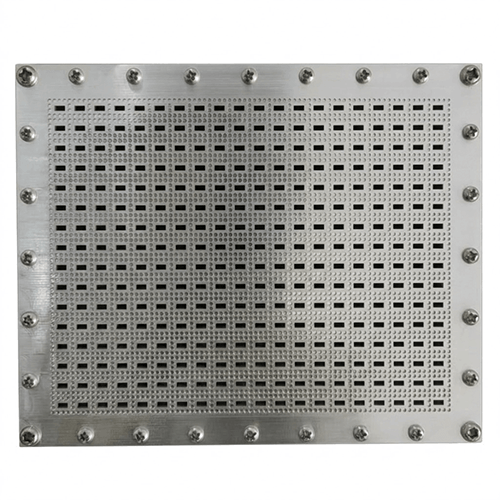
1. Technical Requirements for mmWave Slot Array Antennas
The millimeter-wave spectrum typically spans from 30 GHz to 300 GHz, with corresponding wavelengths ranging from 1 mm to 10 mm. Within this high-frequency band, the dimensional accuracy of waveguide components must often reach sub-millimeter or even micron levels to ensure efficient signal transmission with minimal loss.
TYPICAL TOLERANCE STANDARDS
| Frequency Band | Slot Dimension Tol. | Slot Spacing Tolerance |
| 30~60GHz | ±0.02 to ±0.05 mm | ±0.03 to ±0.08 mm |
| 60~100GHz | ±0.015 to ±0.03 mm | ±0.03 to ±0.08 mm |
| >100GH | Approx. ±0.01 mm | ±0.03 to ±0.08 mm |
Critical Impact: Any deviation exceeding these tolerance ranges will lead to radiation pattern distortion and significant gain degradation.
To balance excellent electrical conductivity, low weight, and machinability, these parts are typically fabricated from aluminum alloys or copper alloys. Their internal cavities demand stringent surface roughness standards to minimize signal attenuation:
Below 30 GHz:Ra ≤0.8um
30 GHz to 100 GHz:Ra0.4 to 0.6um
Above 100 GHz (EHF):Ra0.2 to 0.4um
Adding to the complexity, the internal waveguide cavities are rarely simple geometric shapes. Instead, they feature intricate 3D spatial configurations, including tapered cross-sections, curved paths, and impedance-matching structures, which further elevates manufacturing difficulty.
2.Precision Milling and Contouring of Complex Internal Cavities
The primary step in manufacturing mmWave slot waveguide antennas is machining the high-precision internal cavity. To handle complex 3D profiles, 5-axis simultaneous precision CNC milling is widely utilized.
Multi-Axis Machining & FixturingBy simultaneously controlling three linear axes and two rotational axes, a 5-axis machining center allows the cutting tool to approach the workpiece at an optimal orientation. This enables operators to complete most of the complex cavity machining in a single setup, eliminating repositioning errors. For extremely deep cavities or narrow slots, a secondary setup is supported by custom precision fixtures to keep alignment errors under ≤ 0.005mm.
Layered Milling Strategy
To achieve the demanding surface quality required for waveguide interiors, a multi-stage layered milling process is implemented:
1.Rough Machining: Rapidly removes bulk material.
2.Semi-Finishing: Machines close to the final net-shape contour.
3.Finishing: Utilizes small-diameter cutters combined with ultra-high spindle speeds and micro-depths of cut to deliver a mirror-like finish.
Toolpath Optimization & Burr Control
Right-angle and sharp-corner transitions inside the cavity present major machining hurdles. Implementing advanced toolpath strategies—such as trochoidal milling or helical interpolation—ensures smoother cutting actions in these critical zones, mitigating tool vibration and securing tight contour accuracy.
Furthermore, aluminum and copper are highly prone to burr formation along cavity edges and slots. Burr generation can be significantly suppressed by applying the following optimized parameters alongside tool edge treatments (such as passivation and polishing):
Spindle Speed (Aluminum): 10,000 to 25,000 RPM
Spindle Speed (Copper): 8,000 to 20,000 RPM
Depth of Cut(ap):0.02 to 0.1 mm
3.High-Consistency Machining of Micro-Hole Arrays
The radiation performance of a slot waveguide antenna depends heavily on the quality of its surface micro-hole array. These micro-holes typically have diameters between 0.2 mm and 0.8 mm, with aspect ratios ranging from 3:1 to 8:1. Holes with an aspect ratio≥6:1 fall into the category of challenging deep micro-hole machining.
MICRO-HOLE SPECIFICATIONS
| Feature | Standard Range |
| Hole Diameter | 0.2 mm to 0.8 mm |
| Typical Aspect Ratio | 3:1 to 8:1 |
| Deep Micro-Hole Threshold | ≥ 6:1 |
For hole diameters under 0.5 mm, conventional mechanical drilling often causes tool deflection or breakage. To counter this, Micro-Electrical Discharge Machining offers unique advantages:
Force-Free Machining: Utilizing solid wire electrodes (copper or tungsten) with diameters of 0.1 to 0.3 mm, Micro-EDM erodes material via pulsed discharges. Because it exerts virtually zero mechanical cutting force, workpiece deformation is eliminated, making it ideal for processing high-hardness alloys.
High-Precision Positioning: To ensure precise alignment across dozens or hundreds of micro-holes, manufacturers combine machine vision positioning with CNC coordinates. Machine vision first identifies datum features to establish an accurate coordinate system. In mass production, positional accuracy is maintained within ±0.01 to ±0.02 mm. When paired with ultra-precision air-bearing fixtures and strict thermal control (20± 0°C), accuracy can reach ±0.005 to ±0.01 mm.
Real-Time Wear Compensation: Diameter consistency is maintained through real-time electrode wear compensation technology. The CNC system dynamically adjusts machining depth based on discharge status and wear models, compensating for any electrode erosion.
Flushing and Heat Dissipation: Debris clearance is the main bottleneck in high-aspect-ratio hole drilling. Implementing a periodic peck-drilling (retraction) strategy allows dielectric fluid to enter the hole efficiently, flushing out eroded particles and cooling the zone to prevent electrode sticking.
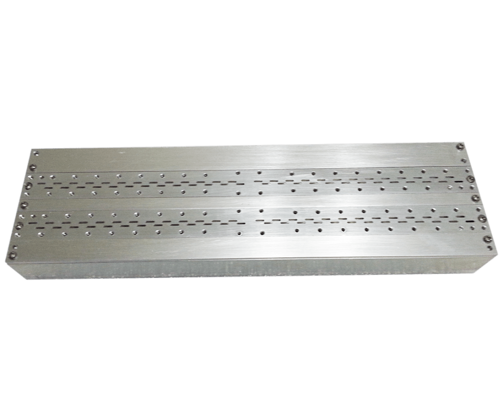
4. Multi-Dimensional Quality Inspection and Closed-Loop Process Optimization
Comprehensive quality inspection is critical to validating the final RF performance of mmWave slot array antennas, requiring a blend of advanced metrology techniques.
Cavity Metrology
Open Cavities: For wide-opening internal cavities with excellent feature visibility, non-contact laser scanning or structured light 3D scanning is preferred.
Deep/Narrow Cavities: For hidden features, contact Coordinate Measuring Machines (CMM) equipped with specialized ruby probes or Industrial CT Scanning are utilized. These methods capture complete point cloud data or exact dimensional coordinates to evaluate volumetric and form errors against the original CAD model.
Micro-Hole Array Metrology
Micro-hole inspection focuses on positional accuracy and geometric integrity. High-resolution industrial cameras equipped with machine vision algorithms automatically locate the center of each hole and calculate deviations from theoretical positions. Hole diameters and roundness are further verified using miniature bore gauges or fiber-optic probes.
Surface Roughness Verification
White light interferometry is the industry standard for roughness testing. Its nanometer-level vertical resolution precisely maps the topography of internal cavity walls and micro-hole interiors.

The data collected is not just for QA pass/fail metrics; it drives closed-loop process optimization. For instance, if an inspection detects localized high roughness, engineers trace the root causes (e.g., tool wear, coolant delivery, or machine vibration) and adjust local milling parameters—such as increasing spindle speed, reducing feed rates, or optimizing toolpaths.
Similarly, systematic deviations in micro-hole positioning prompt checks for machine thermal deformation or fixture misalignment. This data-driven, iterative optimization loop is the core foundation for ensuring quality consistency in high-volume production.
Conclusion
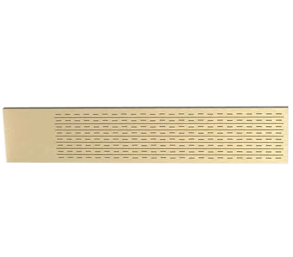
When these millimeter-wave slot array antennas are integrated into 5G base stations and satellite communication payloads, their precision-machined slots begin to radiate electromagnetic waves with high efficiency, forming the high-speed communication fabrics that link cities to rural areas, and the earth to space.
Emitted from micro-holes less than half a millimeter in diameter, these mmWaves propagate with meticulously controlled phase and amplitude. These micro-structures, barely visible to the naked eye, serve as the definitive cornerstone pushing wireless communications into higher frequency bands and broader bandwidths.