
If you work in RF, microwave, or millimeter-wave engineering, you have probably seen these connector names on a BOM and paused for a second: “1.0 mm, 1.85 mm, 2.4 mm, 2.92 mm, 3.5 mm… Is this a password, a lunch order, or an RF connector family?”
The answer is much less mysterious: these numbers are the names of precision millimeter-wave connectors, and they are based directly on the connector’s internal outer conductor diameter.
In other words, RF engineers did not hide the meaning in a complicated code. They simply put the size right into the name.
The Name Is the Size, and the Size Determines the Frequency
The naming rule is refreshingly straightforward: the number in the connector name indicates the inner diameter of the outer conductor in the air dielectric section.
3.5 mm connector — 3.5 mm outer conductor inner diameter; typically used up to 33 GHz.
2.92 mm connector — 2.92 mm outer conductor inner diameter; typically used up to 40 GHz.
2.4 mm connector — 2.4 mm outer conductor inner diameter; typically used up to 50 GHz.
1.85 mm connector — 1.85 mm outer conductor inner diameter; typically used up to 67 GHz.
1.0 mm connector — 1.0 mm outer conductor inner diameter; typically used up to 110 GHz.
The rule of thumb is simple: the smaller the number, the higher the usable frequency, and the smaller the connector.
Think of it as the millimeter-wave connector upgrade path: 3.5 mm is the entry point, 2.92 mm and 2.4 mm move into higher frequencies, 1.85 mm reaches the 67 GHz range, and 1.0 mm takes you into the 110 GHz territory.
Why Can’t SMA Handle Everything?
A common question is: “SMA connectors can handle microwave frequencies, and precision SMA can reach 26.5 GHz. Why do we need all these additional connector types?”
The reason is that higher frequencies mean shorter wavelengths, and shorter wavelengths make the connector’s dimensional tolerances much more critical.
Standard SMA connectors typically use PTFE dielectric support. In contrast, the common millimeter-wave connector families — 3.5 mm, 2.92 mm, 2.4 mm, 1.85 mm, and 1.0 mm — generally use air dielectric structures. Air has a dielectric constant much closer to 1, which helps reduce dielectric loss and signal reflection at high frequencies.
A simple analogy:
SMA is like a reliable city road: excellent for many microwave applications.
Millimeter-wave connectors are like precision race tracks: the lane width, surface smoothness, and alignment must all be much more exact.
At millimeter-wave frequencies, the question is not only “Can these connectors mate?” but also “Will the RF performance remain stable after mating?”
Which Connectors Can Mate with Each Other?
This is where many RF engineers have learned an expensive lesson: millimeter-wave connectors can look very similar, but they are not always mechanically or electrically interchangeable.
3.5 mm and 2.92 mm: Compatible Family
These two connectors can mechanically mate. The 3.5 mm connector is a precision metrology-grade standard, while the 2.92 mm connector can be viewed as a higher-frequency evolution of the same general interface family. In overlapping frequency ranges, they can also perform electrically.
2.92 mm and SMA: They Can Mate, but Be Careful
This is the “looks compatible, but proceed with caution” pairing. SMA connectors are generally manufactured with looser tolerances than 2.92 mm connectors. Repeatedly mating an SMA male connector with a 2.92 mm female connector can damage the precision interface.
A practical rule: avoid mixing SMA and 2.92 mm connectors whenever possible. If mixed mating is unavoidable, use a suitable adapter as a sacrificial interface.
2.4 mm and 1.85 mm: Another Compatible Family
The 2.4 mm and 1.85 mm connectors can mate with each other. However, they are not compatible with the 3.5 mm / 2.92 mm family. For example, a 2.4 mm male connector will not fit into a 2.92 mm female connector because the physical dimensions are different.
1.0 mm: The Lone Specialist
The 1.0 mm connector supports frequencies up to 110 GHz and is commonly used in W-band applications. It is not mechanically compatible with the other connector families discussed above. Its center conductor is extremely small, so assembly and cleaning are often performed under magnification.
A quick compatibility summary:
3.5 mm / 2.92 mm / SMA: a related family, but precision levels differ.
2.4 mm / 1.85 mm: another compatible family.
1.0 mm: a separate interface family; it does not mate with the others.
Connector Selection Pitfalls to Avoid
Pitfall 1: Mixed Mating Damages the Interface
A 2.92 mm female connector repeatedly mated with an SMA male connector may lose interface precision, causing RF performance degradation and potentially requiring repair or replacement.
Pitfall 2: Improper Cleaning
Millimeter-wave connector center conductors are extremely delicate, especially in 1.0 mm connectors. Dust or metal particles can create dents or scratches during mating. Use lint-free swabs and isopropyl alcohol for cleaning; avoid wiping with ordinary paper tissues.
Pitfall 3: Incorrect Torque
Each connector type has a specified mating torque. Excessive torque can damage the interface, while insufficient torque can lead to poor electrical contact. Using a calibrated torque wrench is standard practice for precision RF connectors.
Pitfall 4: Looking Only at Frequency, Not Compatibility
Selecting a connector solely because it supports the required frequency can create practical problems if your existing calibration kits, cables, or test equipment use a different connector interface.
Before selecting a connector, confirm:
The required operating frequency range.
The connector interfaces used by your existing cables, calibration kits, and test equipment.
Whether adapters will be required for system integration.
The Takeaway: Millimeter-Wave Connectors Are Small, but They Matter
The logic behind millimeter-wave connectors is actually quite simple:
The name reflects the physical size.
The size determines the frequency capability.
The frequency capability determines the required precision.
Smaller connector sizes generally support higher frequencies, but they also demand tighter machining tolerances, cleaner handling, proper torque control, and careful interface protection.
So the best selection strategy is not “choose the smallest connector possible.” It is choose the connector family that matches the required frequency, system compatibility, and precision requirements.
Precision Machining for Millimeter-Wave Systems
In millimeter-wave systems, connector selection is only part of the equation. The performance of the entire RF signal chain also depends on the machining accuracy, surface treatment, and interface consistency of waveguide components and related precision structures.
About Chengdu Taihezhi Technology Co., Ltd.
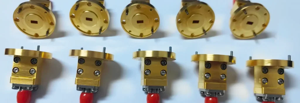
Chengdu Taihezhi Technology Co., Ltd. specializes in high-precision machining for microwave, millimeter-wave, and terahertz applications. The company provides customized manufacturing services for waveguide components, waveguide adapters, waveguide assemblies, cavities, flanges, and other precision RF structures.
With extensive experience in precision machining, Chengdu Taihezhi Technology Co., Ltd. supports frequency ranges from 8.2 GHz to 1000 GHz and is capable of manufacturing complex waveguide structures and millimeter-wave test components.
Just as with millimeter-wave connectors, the dimensional accuracy, surface finish, and interface alignment of waveguide components are critical factors in achieving stable high-frequency RF performance.
So while these connectors may look like tiny silver hardware, they are far from insignificant. In a millimeter-wave system, a single connector interface or waveguide flange can influence the performance of the entire RF signal chain.