
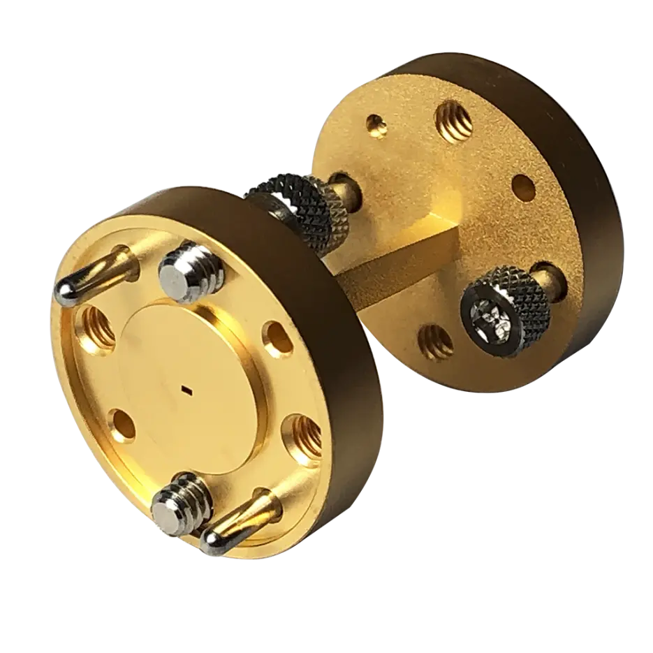
The WR2.8 twist waveguide operates in the 220–325 GHz band.
With an internal cross-section of only 0.71 × 0.355 mm, WR2.8 belongs to the Millimeter wave regime where every micron matters.
At these frequencies, even a slight geometric deviation—such as a few microns in cavity size or a fractional-degree twist-angle error—will immediately degrade:
Insertion Loss
Return Loss / VSWR
Mode purity
Polarization accuracy
Unlike a straight waveguide, a WR2.8 twist waveguide contains a complex 3D rotational transition, making it far more challenging to machine with consistency.
To achieve stable and repeatable electrical performance in high-volume production, we developed a dedicated fixturing system specifically designed for WR2.8 twist-waveguide machining.
This fixture is now one of our strongest competitive advantages.
Part 1 — Why WR2.8 Twist Waveguides Are Extremely Difficult to Manufacture
- Ultra-small cavity requires micron-level accuracy
The Millimeter cross-section demands:
Extremely rigid micro-tools
Perfect toolpath control
Zero clamping runout
Precise plating thickness
Any dimensional deviation of just a few microns produces measurable RF degradation.
- 3D rotational geometry must maintain cavity uniformity
A WR2.8 twist waveguide transitions smoothly from 0° to 90°.
The cavity must:
Maintain a clean rectangular shape
Rotate uniformly without steps or discontinuities
Avoid distortions that generate higher-order modes
Geometry smoothness directly affects mode purity.
- Twist-angle accuracy must be extremely tight
Twist-angle error leads to:
Polarization mismatch
Increased loss
Mechanical misalignment during assembly
At WR2.8, angle accuracy must be controlled within ±0.5° or tighter.
- Surface roughness requirements are demanding
At 220–325 GHz:
Internal surface roughness must be Ra ≤ 0.2–0.4 μm
Any increase in roughness dramatically raises conductor loss
Measured S21 performance is very sensitive to surface quality
- Micro-size workpieces are extremely difficult to clamp stably
WR2.8 parts are:
Thin
Lightweight
Sensitive to stress and vibration
Conventional fixtures cannot guarantee:
Stable twist-angle
Cavity coaxiality
Deformation control during machining
Without a proper fixture, stable production is impossible.
Part 2 — Our Solution: A Dedicated Fixturing System for WR2.8 Twist-Waveguide Machining
To fundamentally solve the stability and repeatability issues in WR2.8 twist machining, we designed and manufactured a specialized twist-waveguide fixture.
This system integrates multi-axis mechanical alignment, force balancing, anti-deformation structures, and micron-level positioning.
- Micron flange-alignment system
Using precision locating pins and controlled flange clamping, our fixture:
Maintains coaxiality between both ends of the waveguide
Controls clamping deviation within ±0.005–0.01 mm
Prevents angular drift during machining
- Twist-angle locking mechanism
A micro-angle locking system ensures:
Stable 3D twist angle through the entire machining process
Twist-angle accuracy better than ±0.5°
Zero rotational drift under cutting forces
- Anti-deformation compensation structure
To counteract bending and stress during machining, the fixture uses:
Symmetrical support structures
Elastic compensation zones
Multi-point constraint
This ensures high straightness along the entire 1-inch length.
- Micro-rigidity control for ultra-small parts
The fixture includes:
Multi-point micro-supports
Low-interference jaws
Force-distribution structures
This prevents:
Outer-wall damage
Twist-section distortion
Cavity misalignment
- Fully repeatable clamping for batch production
With the dedicated fixture:
Each workpiece is positioned identically
Batch-to-batch consistency improves significantly
Insertion-loss repeatability increases by 15–25% compared with conventional setups
This is a major advantage for mmWave/THz customers requiring consistent performance.