
From 0.25 × 0.125 mm Waveguide Apertures to Fully Functional Sub-THz Components
WR1.0 Is Not “Small Size.” It Is “Extreme Manufacturing.”
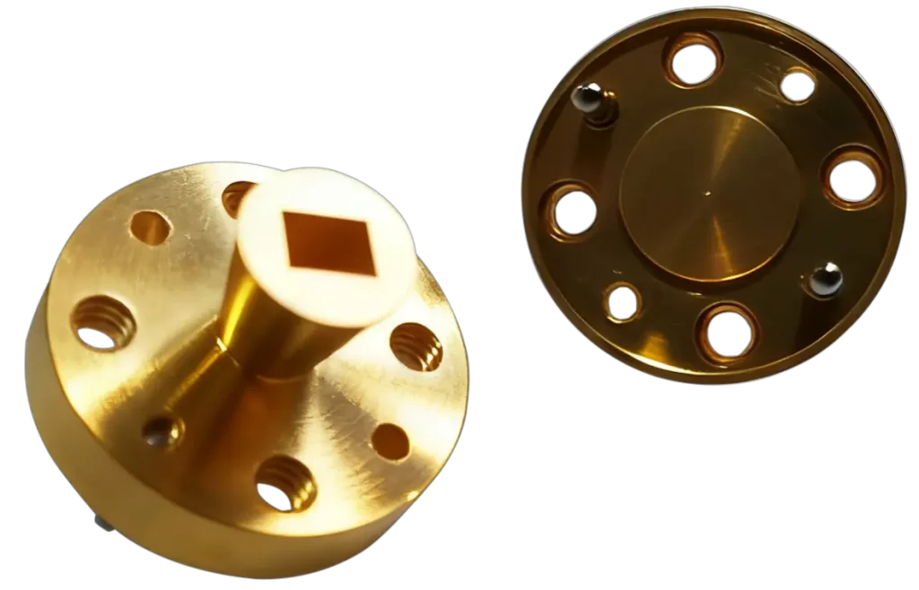
In the 750–1100 GHz band, a WR1.0 waveguide aperture measures only:0.25 mm × 0.125 mm(250 μm × 125 μm)
At this scale:
Manufacturing tolerances approach 1/3 to 1/5 of a human hair
Any 3–5 μm deviation can cause
mode distortion, increased reflection, and higher insertion loss
Surface roughness, corner radius (R), and split-block alignment
directly determine RF performance and repeatability
This is why only a handful of suppliers globally
can machine structures reliably at the WR1.0 level.
THZ Precision not only machines a single structure,
but delivers the entire WR1.0 waveguide ecosystem, including:
✔ Straight Waveguide
✔ E-bend / H-bend
✔ Twist Waveguide
✔ Step Transition / Linear Taper / Profiled Transition
✔ Standard Gain Horns
✔ Custom RF/Microwave Sub-THz Modules
This is not mere manufacturability—
it is scalable, repeatable manufacturing across the full chain.
Technical Challenges:
Why Every WR1.0 Structure Exceeds Traditional Precision Machining Limits
1. With a 0.125 mm Cross-Section, the Tool Is Larger Than the Waveguide Itself
Standard machining cannot solve:
Micro-tool strength limitations
Tool-tip radius too large
Insufficient rigidity
Frequent chipping and breakage
No conventional cutter can physically enter a 125 μm-wide waveguide.
THZ Precision overcomes this through:
Custom micro-tools (non-commercial)
RF-aware toolpath design
Effective tool-tip radius approaching zero
Allowing us to machine deep into the WR1.0 geometry.
2. Creating E/H Bends at the 0.1 mm Scale Is a Cross-Disciplinary Challenge
A bend is not “just a curve.”
In sub-THz frequencies, it is an engineering constraint involving:
Wall-thickness stress balance
Local deformation control
Internal cavity uniformity
Field guidance for modal preservation
Traditional workshops cannot predict E/H-plane field behavior.
THZ Precision designs bends that maintain:
Mode purity
Low insertion loss
Stable phase characteristics
3. Twist Waveguides Demand Exceptional Corner and Wall Consistency
A twist must simultaneously achieve:
Uniform twist angle
No internal steps
No local field bulge
Minimal surface scattering
Controlled split-line geometry
This capability is unattainable for standard machine shops.
4. Transitions Require Dual Optimization:
Machining Accuracy + Electromagnetic Behavior
WR1.0 transitions must have:
Continuous curvature
Controlled cross-sectional evolution
Extremely low surface roughness
No geometric “field traps”
This requires true understanding of both
precision metalcutting and high-frequency EM design.
5. Horn Antennas Near 1 THz Represent the Peak of Manufacturing Difficulty
The horn throat dimensions are comparable to micro-features.
Small deviations cause:
Sidelobe rise
Beam pointing errors
Gain reduction
Pattern asymmetry
Only teams that understand both EM and machining
can deliver usable 1 THz horns.
6. Custom Modules = High-Frequency Structures + Multi-Cavity Geometry + Split-Block Assembly
A module is not “just a block.”
It involves:
RF topology
Multi-stage cavity networks
Inter-channel alignment
Split-block compensation
Assembly repeatability
This is a higher level of capability than parts machining.
THZ Precision’s Solution (Certainty Logic)
1. RF-Aware Micro-Machining Architecture
We do not machine “geometry.”
We machine:
Field paths
Mode boundaries
Power concentration zones
High-frequency sensitive regions
This is why we say—
we do not just cut metal; we understand waveguides
2. Custom Micro-Tool Library (Non-Commercial)
For WR1.0 we developed:
Ultra-short micro endmills
Special tool-tip geometry
Near-zero effective radius
Sub-THz specific coatings
Anti-chatter toolpath strategies
These tools do not exist in traditional shops.
3. Ultra-Precision Machining:
±0.003 mm (3 μm) Stable Control**
For WR1.0 cavities, we achieve:
Wall parallelism: ≤ 3–5 μm
Corner deviation: ≤ 3 μm
Surface roughness: Ra 0.1–0.2 μm
Split-block alignment: < 5 μm
All surpassing slow-wire EDM by two to three finishing grades.
WR1.0 is not small in size—
it is deep in dimension and complexity.
It tests not only machines, but also:
Understanding of electromagnetic fields
Material behavior
Tool dynamics
Stress control
Surface integrity
Assembly physics
This is why THZ Precision can manufacture the complete WR1.0 ecosystem—
from straight sections to horns, from transitions to modules,from 750 GHz to 1.1 THz.