
In millimeter-wave and terahertz waveguide systems, two issues are most likely to compromise performance during assembly:
Micro-warping of the flange surface, leading to imperfect contact and degraded electrical performance (higher return loss / insertion loss).
Stress concentration during tightening, resulting in long-term deformation or distortion around screw holes.
The structural difference between Anti-Cocking Flanges and Standard Flat-Edge Flanges directly determines how effectively these risks can be controlled.
Structural Features & Installation Advantages
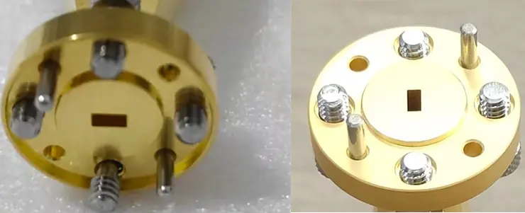
① Reinforced outer ring with equal-height platform
Anti-Cocking flanges incorporate a raised, equal-height structural ring around the screw area.
This ring:
Distributes tightening force
Prevents local bending around screw holes
Avoids “edge lifting” (warping) when torque is applied
② More resistant to deformation during installation
At mmWave and THz frequencies—especially WR6, WR3, WR2.2 and smaller—
even microns of flange distortion can misalign the waveguide aperture and impact S-parameters.
The reinforced outer ring helps maintain:
Improved flatness
Better surface contact
Higher stability under ±0.003 mm machining tolerances (your company’s strong point)
③ Higher assembly tolerance and less torque sensitivity
In real assembly conditions:
Under-tightening may cause leakage
Over-tightening can easily deform a standard flange
Anti-Cocking flanges mitigate these risks, offering higher robustness and more installation flexibility.
2. Standard Flat-Edge Flange
— Installation Limitations
① More prone to local warping under screw pressure
Without a reinforced ring:
The screw area can be pressed downward
The outer edge may be pulled upward
Contact surface may lose full flatness
At high frequencies, such distortion leads to:
Aperture misalignment
Micro-gaps at the flange interface
Increased insertion loss and degraded VSWR
② Requires precise torque control and tightening sequence
Standard flanges demand stricter assembly discipline:
Diagonal tightening
Carefully balanced torque
Controlled tightening order
Any uneven force can cause “banana-shaped” warping.
③ More susceptible to long-term fatigue deformation
This becomes evident in:
Frequent mounting/dismounting
Thermal cycles
Vibration environments
Smaller flange sizes (WR10–WR2.2)
Their lifespan and stability are generally lower compared with Anti-Cocking structures.
3.Application Differences
| Aspect | Anti-Cocking Flange | Standard Flat-Edge Flange |
| Installation Stability | Excellent | Moderate |
| Tolerance to Torque Variation | High | Low |
| Electrical Performance Stability | Superior | Easily affected by deformation |
| Best For | WR12 and below, high-frequency systems, precision labs, satellite payloads, performance-critical interfaces | Cost-sensitive projects or lower-frequency applications |
| Long-Term Reliability | High | Medium to Low |
4.Executive Summary
The Anti-Cocking flange uses a reinforced, equal-height ring to reduce deformation during installation, ensuring a flatter mating surface and more stable electrical performance in high-frequency waveguide systems.
Standard flat-edge flanges lack this structural support, making them more sensitive to torque variations and more prone to local warping both during installation and over long-term use.