Waveguide Straight Section
Description
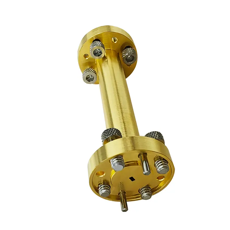
The M series waveguides are precision machined from a single solid metal block.
This monolithic manufacturing process eliminates the risk of RF leakage and mechanical misalignment commonly associated with split-block assemblies.Designed for high-frequency applications up to WR-1.0.
The M series provides high mechanical integrity, stable phase performance, and minimized insertion loss for demanding instrumentation setups.
Features & Customization
Accuracy: High-precision EDM and machining processes enable tight dimensional tolerances.
Lengths: Standard lengths are available, with custom lengths offered upon request to accommodate specific system layouts.
Materials: Brass,Tellurium Copper,Stainless Steel Surface Finish: Gold plating, Silver plating, or Passivation available.
Flange Interface: Equipped with standard compatible flanges (e.g., UG-Style).
Dimensional Specifications
| Model P/N | Waveguide | Frequency (GHz) | VSWR | Flange Interface | Standard Length (mm) | Maximum Length (mm) | Material | Finish |
|---|---|---|---|---|---|---|---|---|
| SW-1.0-25.4-M | WR-1.0 | 750 - 1100 | ≤1.15 | UG-387/U-M (APF1.0) | 25.4 | 25.4 | Brass | Gold Plated |
| SW-1.2-25.4-M | WR-1.2 | 600 - 900 | ≤1.15 | UG-387/U-M (APF1.2) | 25.4 | 25.4 | Brass | Gold Plated |
| SW-1.5-25.4-M | WR-1.5 | 500 - 750 | ≤1.15 | UG-387/U-M (APF1.5) | 25.4 | 25.4 | Brass | Gold Plated |
| SW-1.9-25.4-M | WR-1.9 | 400 - 600 | ≤1.15 | UG-387/U-M (APF1.9) | 25.4 | 25.4 | Brass | Gold Plated |
| SW-2.2-25.4-M | WR-2.2 | 330 - 500 | ≤1.15 | UG-387/U-M (APF2.2) | 25.4 | 50.8 | Brass | Gold Plated |
| SW-2.8-25.4-M | WR-2.8 | 260 - 400 | ≤1.15 | UG-387/U-M (APF2.8) | 25.4 | 50.8 | Brass | Gold Plated |
| SW-03-25.4-M | WR-3 | 217 - 330 | ≤1.15 | UG-387/U-M (APF3) | 25.4 | 50.8 | Brass | Gold Plated |
| SW-04-25.4-M | WR-4 | 172 - 260 | ≤1.15 | UG-387/U-M (APF4) | 25.4 | 50.8 | Brass | Gold Plated |
| SW-05-25.4-M | WR-5 | 145 - 220 | ≤1.15 | UG-387/U-M | 25.4 | 50.8 | Brass | Gold Plated |
| SW-06-25.4-M | WR-6 | 110 - 170 | ≤1.15 | UG-387/U-M | 25.4 | 50.8 | Brass | Gold Plated |
| SW-08-25.4-M | WR-8 | 90 - 140 | ≤1.15 | UG-387/U-M | 25.4 | 100 | Brass | Gold Plated |
| SW-10-25.4-M | WR-10 | 70 - 110 | ≤1.15 | UG-387/U-M | 25.4 | 100 | Brass | Gold Plated |
| SW-12-25.4-M | WR-12 | 60 - 90 | ≤1.15 | UG-387/U | 25.4 | 100 | Brass | Gold Plated |
| SW-15-25.4-M | WR-15 | 49.8 - 75.8 | ≤1.15 | UG-385/U | 25.4 | 100 | Brass | Gold Plated |
| SW-19-25.4-M | WR-19 | 39.2 - 59.6 | ≤1.15 | UG-383/U-M | 25.4 | 100 | Brass | Customized |
| SW-22-25.4-M | WR-22 | 32.9 - 50 | ≤1.15 | UG-383/U | 25.4 | 100 | Brass | Passivated |
| SW-28-25.4-M | WR-28 | 26.5 - 40.0 | ≤1.10 | UG-599/U | 25.4 | 100 | Brass | Passivated |
| SW-34-25.4-M | WR-34 | 21.7 - 33 | ≤1.10 | UBR 260 | 25.4 | 100 | Brass | Passivated |
| SW-42-25.4-M | WR-42 | 17.6 - 26.7 | ≤1.10 | UG-595/U | 25.4 | 100 | Brass | Passivated |
Description
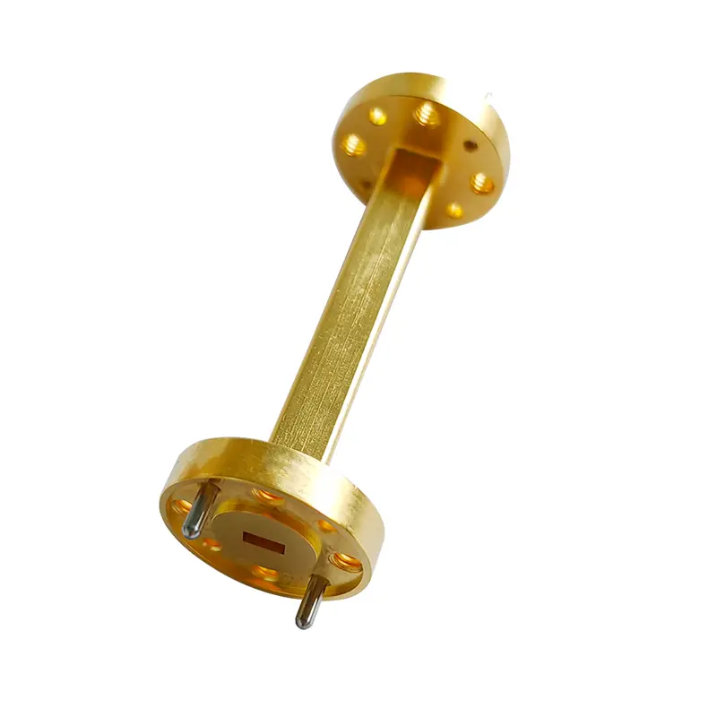
The S series consists of precision-manufactured straight rectangular waveguide sections produced from high-quality waveguide tube.
These components are intended for microwave and millimeter-wave transmission systems where stable mechanical interfaces, dimensional consistency, and reliable RF performance are required.
The S series provides a practical and cost-effective solution for standard waveguide interconnections across commonly used frequency bands.
Features & Customization
Construction: Precision drawn waveguide tube with brazed flanges for mechanical stability.
Custom Lengths: Standard lengths are available, with custom lengths offered upon request to accommodate specific system layouts.
Materials: Copper body with Brass flanges.
Surface Finish: Gold plating, Silver plating, or Passivation available.
Flange Interface: Equipped with standard compatible flanges (e.g., UG-Style).
Dimensional Specifications
| Model P/N | Waveguide | Frequency Range (GHz) | VSWR (Max) | Flange Interface | Standard Length (mm) | Maximum Length (mm) | Material | Finish |
|---|---|---|---|---|---|---|---|---|
| SW-03-25.4-S | WR-3 | 217 - 330 | ≤1.15 | UG-387/U-M (APF3) | 25.4 | 50.8 | Copper Tube / Brass Flange | Gold Plated |
| SW-04-25.4-S | WR-4 | 172 - 260 | ≤1.15 | UG-387/U-M (APF4) | 25.4 | 270 | Copper Tube / Brass Flange | Gold Plated |
| SW-05-25.4-S | WR-5 | 145 - 220 | ≤1.15 | UG-387/U-M | 25.4 | 350 | Copper Tube / Brass Flange | Gold Plated |
| SW-06-25.4-S | WR-6 | 110 - 170 | ≤1.15 | UG-387/U-M | 25.4 | 500 | Copper Tube / Brass Flange | Customized |
| SW-08-25.4-S | WR-8 | 90 - 140 | ≤1.15 | UG-387/U-M | 25.4 | 500 | Copper Tube / Brass Flange | Gold Plated |
| SW-10-25.4-S | WR-10 | 70 - 110 | ≤1.15 | UG-387/U-M | 25.4 | 500 | Copper Tube / Brass Flange | Gold Plated |
| SW-12-25.4-S | WR-12 | 60 - 90 | ≤1.15 | UG-387/U | 25.4 | 500 | Copper Tube / Brass Flange | Gold Plated |
| SW-15-25.4-S | WR-15 | 49.8 - 75.8 | ≤1.15 | UG-385/U | 25.4 | 500 | Copper Tube / Brass Flange | Gold Plated |
| SW-19-25.4-S | WR-19 | 39.2 - 59.6 | ≤1.15 | UG-383/U-M | 25.4 | 500 | Copper Tube / Brass Flange | Gold Plated |
| SW-22-25.4-S | WR-22 | 32.9 - 50 | ≤1.15 | UG-383/U | 25.4 | 500 | Copper Tube / Brass Flange | Gold Plated |
| SW-28-25.4-S | WR-28 | 26.5 - 40.0 | ≤1.10 | UG-599/U | 25.4 | 500 | Copper Tube / Brass Flange | Gold Plated |
| SW-34-25.4-S | WR-34 | 21.7 - 33 | ≤1.10 | UG-1530/U | 25.4 | 500 | Copper Tube / Brass Flange | Gold Plated |
| SW-42-25.4-S | WR-42 | 17.6 - 26.7 | ≤1.10 | UG-595/U | 25.4 | 500 | Copper Tube / Brass Flange | Gold Plated |
Why Choose Our M-Series Precision Machined Waveguides?
1. Monolithic Manufacturing Excellence:
M-series waveguides are CNC milled from a single solid metal block. This seamless design completely eliminates the risk of RF leakage at millimeter-wave and terahertz frequencies (up to 1100 GHz), ensuring exceptional signal integrity and minimum insertion loss.
2. Micron Precision & Micro-Slot Machining: Utilizing advanced high-precision wire EDM and CNC milling techniques, we maintain rigid the key dimensional tolerances down to ±0.005mm. For ultra-high frequency models (such as WR-1.0 and WR-1.2), our specialized tooling paths prevent any structural deformation in extremely narrow slots, ensuring consistent phase performance for demanding instrumentation setups.
3. Premium Materials & Surface Finish: Available in Aluminum, Stainless steel, Brass,Oxygen-Free Copper, and C14500 Tellurium Copper. To achieve optimal electrical conductivity and prevent oxidation in high-frequency transmission, we offer precise Gold Plating and Silver Plating with strictly controlled surface roughness (Ra).
Note:All designs are independently developed based on industry standards and are not derived from any customer-specific drawings,and OEM customization is available upon request.
Technical Advantages of S-Series Straight Waveguides
Precision-Drawn Waveguide Tubing: The S-series utilizes high-quality, precision-drawn rectangular waveguide tubes that guarantee excellent inner-dimension consistency. This provides a highly practical and cost-effective solution for standard microwave and millimeter-wave interconnections without sacrificing RF performance.
Robust Brazing & Alignment Technology: The waveguide tubes are brazed to standard compatible flanges (such as UG-387/U-M) using custom-designed alignment fixtures. This specialized brazing process ensures high mechanical stability and eliminates mechanical misalignment at the joints, keeping the maximum VSWR under 1.15 across the entire frequency range.
Customization & Versatility: We support custom length extensions (up to 500 mm for specific models) and tailored flange interfaces to accommodate complex system layouts.
Material Selection Guide for Microwave & Terahertz Precision Machining
| Material | Electrical / Thermal Conductivity | CNC Milling & Turning | Wire Cutting | Surface Roughness Control | Typical Applications & Advantages | Relative Cost |
|---|---|---|---|---|---|---|
| Oxygen-Free Copper (e.g., TU1/TU2, C10100) | Excellent(>100% IACS) | Extremely DifficultThe material is very soft and gummy, making it prone to burrs during deep cavity milling. Requires highly optimized tool paths. | FairMachining speed is relatively slow, and the cut surface is susceptible to microscopic deformation. | Difficult to achieve an ultimate mirror finish; requires extremely strict process control. | High-power transmission, ultra-low insertion loss requirements, ultra-high vacuum (UHV) environments, and deep space exploration. | Moderate |
| Brass H62 | Moderate(~28% IACS) | ExcellentFree-machining copper alloy with excellent chip breaking and low tool wear. | ExcellentHighest discharge machining efficiency, excellent surface finish, and minimal wire breakage. | Easy to obtain a good surface finish. | General commercial radar, standard test and measurement equipment, and low-frequency waveguides with less stringent insertion loss requirements. | Lowest |
| Tellurium Copper C14500(TeCu) | Outstanding(~85%-90% IACS) | Very GoodSmooth cutting, easier to mill than Beryllium Copper. | Good (Slightly inferior to Brass)Due to the distribution characteristics of internal tellurium elements, the discharge cutting speed and surface uniformity are slightly lower than those of brass. | ExcellentExtremely easy to achieve ultra-low surface roughness. | High-precision straight waveguides for mmWave/THz bands, high-volume precision machining, and applications with extremely strict dimensional tolerances. | Higher |
| Beryllium Copper(e.g., C17200) | Good(~20%-50% IACS) | PoorExtremely high hardness (especially after heat treatment). Causes severe end-mill wear, long machining cycles, and is prone to thermal deformation. | GoodElectrical conductivity affects discharge speed to some extent, but overall forming accuracy is stable. | Good, but at a higher cost. | High-stress aerospace environments, waveguide flanges requiring extremely high mechanical strength and wear resistance, and extreme thermal cycling scenarios. | Highest |
| Aluminum Alloy(e.g., 6061-T6) | Good(~43% IACS) | ExcellentLow cutting resistance and excellent chip evacuation. Spindle speeds can be pushed very high, making machining efficiency far superior to all copper alloys and stainless steels. | GoodExtremely fast cutting speed, but prone to aluminum oxide adhesion. Requires high flushing pressure to remove slag; occasional wire breakage may occur. | ExcellentVery easy to achieve Ra 0.4 or lower via high-speed milling. (Note: RF applications require subsequent zincating and silver/gold plating, but gold plating on aluminum is prone to blistering). | The first choice for lightweighting. Airborne/spaceborne radar waveguides, large array antennas, and complex, bulky split-block microwave cavities. (Weighs only 1/3 of copper). | LowestCheap raw material and extremely short machining times. |
| Stainless Steel(e.g., 304/316L) | Extremely Poor(~2.5% IACS) | DifficultHigh toughness makes it extremely prone to "work hardening". Very harsh on cutting tools, resulting in long machining cycles. Deep cavity machining easily causes tool vibration. | GoodVery stable discharge state. The cut surface is extremely flat and uniform, capable of cutting extremely narrow and deep waveguide slots. | GoodCan reach a very high finish, but the time and tooling costs to achieve a mirror finish via milling are far higher than for aluminum and tellurium copper. | Extreme environments and thermal isolation. UHV systems and highly corrosive environments. In cryogenic physics systems, its "extremely poor thermal conductivity" is utilized to block external heat transfer. | HigherModerate material cost, but extremely long machining times and high tool wear. |